Carving Robot Arm Control Simulation
1. Objective
Throughout my Masters degree, I took a series of robotics course. Normally, the last course, Control of Robotic Systems, requires building a physical robot and control for the final project. However, due to COVID-19, all classes were held online, meaning it wasn't possible to physically create a robot. The alternative was to control the robot in simulation.
2. Robot
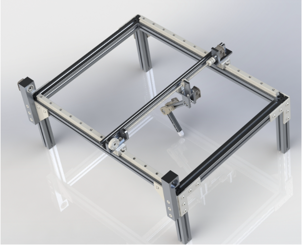
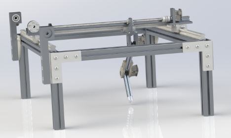
During the earlier course in 263A, Kinematics of Robotics, we designed our robot, named RTiST as shown above. The operating mechanism is similar to a commercial 3D printer mounted on a gantry frame. The two prismatic joints control the x, y position of the end-effector, and the z position is controlled by the 2 revolute joints of the 2-link planar arm.
3. Control Algorithms
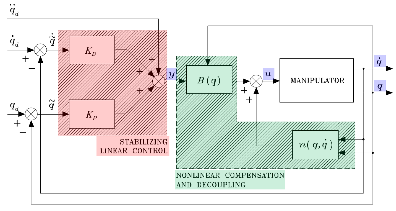
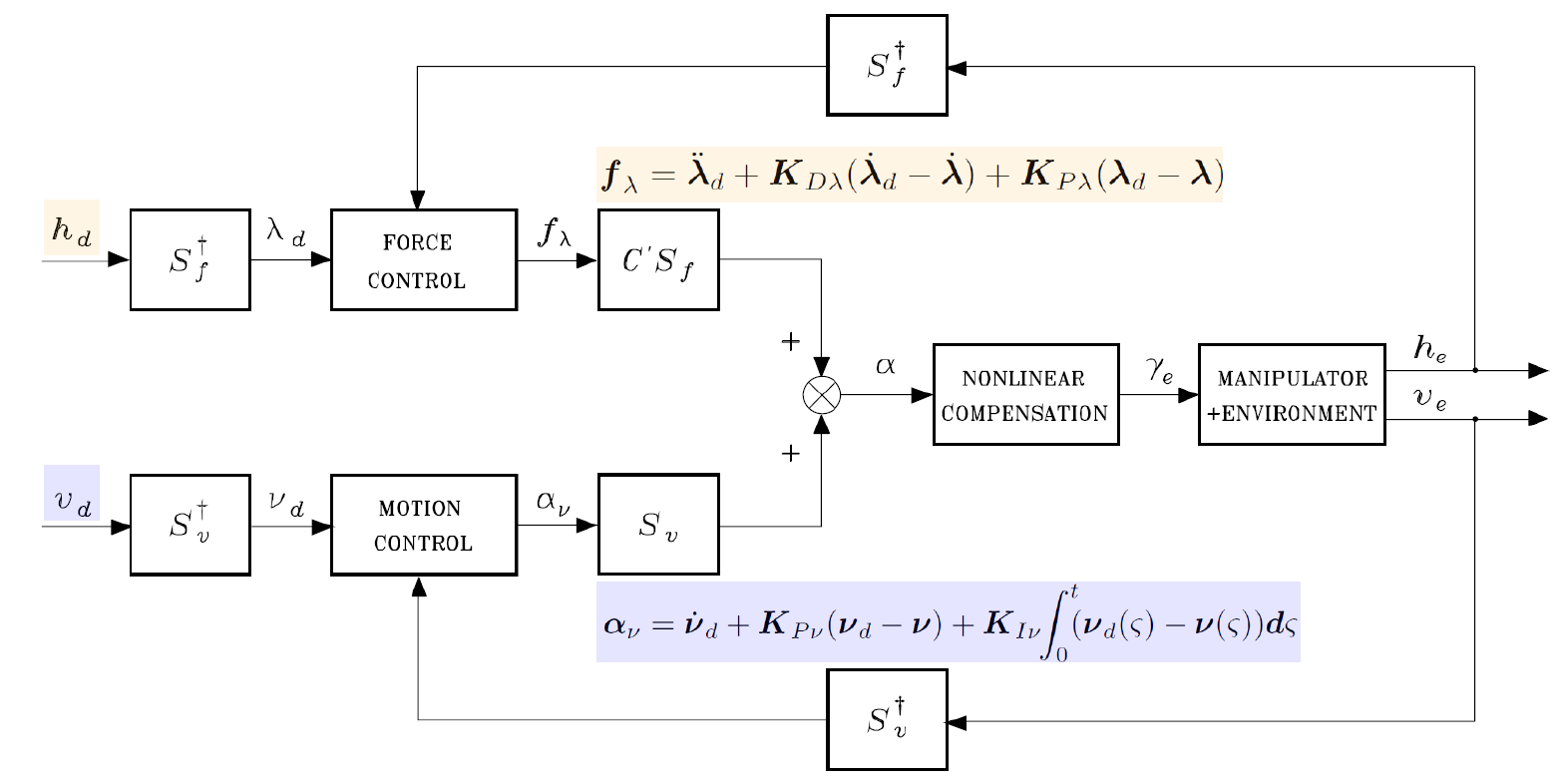
We used two types of control algorithms: Hybrid Force/Motion Control and Joint Space Inverse Dynamics Control. The algorithm flow diagram is shown below.
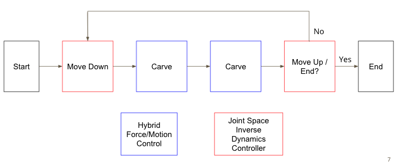
The robot is placed at an initial position. Then, using Joint Space Inverse Dynamics Control, the arm moves down to the top of the block. Once the milling tip reaches the top of the block, the robot uses Hybrid Force/Motion Control to carve back and forth of the line segment. Once it comes back to the original position, the robot then moves up using Joint Space Inverse Dynamics Control, then the cube is re-positioned; this concludes the first carving line segment. Then, this process repeats until the end.
4. Implementation
Since this project was done in simulation, many assummptions had to be considered. 1) The robot moves along the y direciton with no friction. 2) The end effector's x and y positions are fixed. 3) The parameters for the robot and the motors are from Solidworks and from the instructions of the MX-28A motor. 4) The wood used for carving is Cedar, Northern White wood, with the Young's modulus of 4400 MPa.
The initial and final angles are calculated from inverse kinematics of two revolute planar arm, which are then inserted as inputs to the control algorithm. The trajectories have been calculated with a trapezoidal velocity profile. Different values for PID gains were tested with different angular velocities.
The robot is carving the block by 1 cm as it travels in the y-direction. From the video, the bottom left of the simulation shows the trajectory of how the block is being carved; the red line indicates the path that the robot carving is following. After the robot carves by 20 cm, it carves back by 20 cm to come back to the original position. Then, the robot arm moves up to complete the algorithm mentioned above. With the desired contact force, PID gains were calculated and showed minimal velocity errors, which showed stability.
5. Result
The result is shown in the video above.
6. Supplementary Materials
The presentation slide can be found above.
The final report can be found above.